USB Servo Controller
Drive 12 hobby servos from a PC over USB-C. Watches the servo supply and runs scripts on its own.
Ask about availability Source on GitHub
Product and its documentation is supplied on an as-is basis and no warranty as to their suitability for any particular purpose is either made or implied. Producer will not accept any claim for damages howsoever arising as a result of use or failure of this product. This product is not intended for use in any medical appliance, device or system in which the failure of the product might reasonably be expected to result in personal injury.
Description
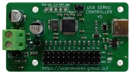
12-channel RC servo controller, an open alternative to the Pololu Mini Maestro 12 that speaks its serial protocols – with USB-C and rail monitoring added. Shows up as a virtual COM port; use Maestro libraries or simple text commands.
- Pololu Maestro compatible: Compact, Pololu and Mini SSC serial protocols with speed and acceleration, so Maestro libraries (Python
maestro.py, ROS drivers…) work unchanged. Maestro Control Center is not supported. - 12 servo outputs at 50 Hz, 0.5 µs resolution; travel limits per channel, 64–4080 µs, stored on the board
- Channels 0–7 can be analog inputs (0–3.3 V)
- Servo rail current and voltage measurement, with overcurrent and undervoltage cut-off
- Scripts stored on the board run without a PC, optionally at power-up
- USB-C virtual COM port, no drivers on Windows 10+, Linux and macOS
- Firmware update over USB, no programmer needed
- Desktop GUI for Windows and Linux: sliders, live current graph, poses and sequences, script editor, one-click firmware update
- Separate servo supply on a screw terminal, up to ~5 A total
- WCH CH32V203 RISC-V MCU, 66 × 38 mm board, 4 × M3 holes
Schematic
USB-C with ESD protection, 3.3 V LDO, CH32V203 MCU, 220 Ω series resistors on every servo signal, and an INA180 shunt amplifier plus divider for rail current and voltage.
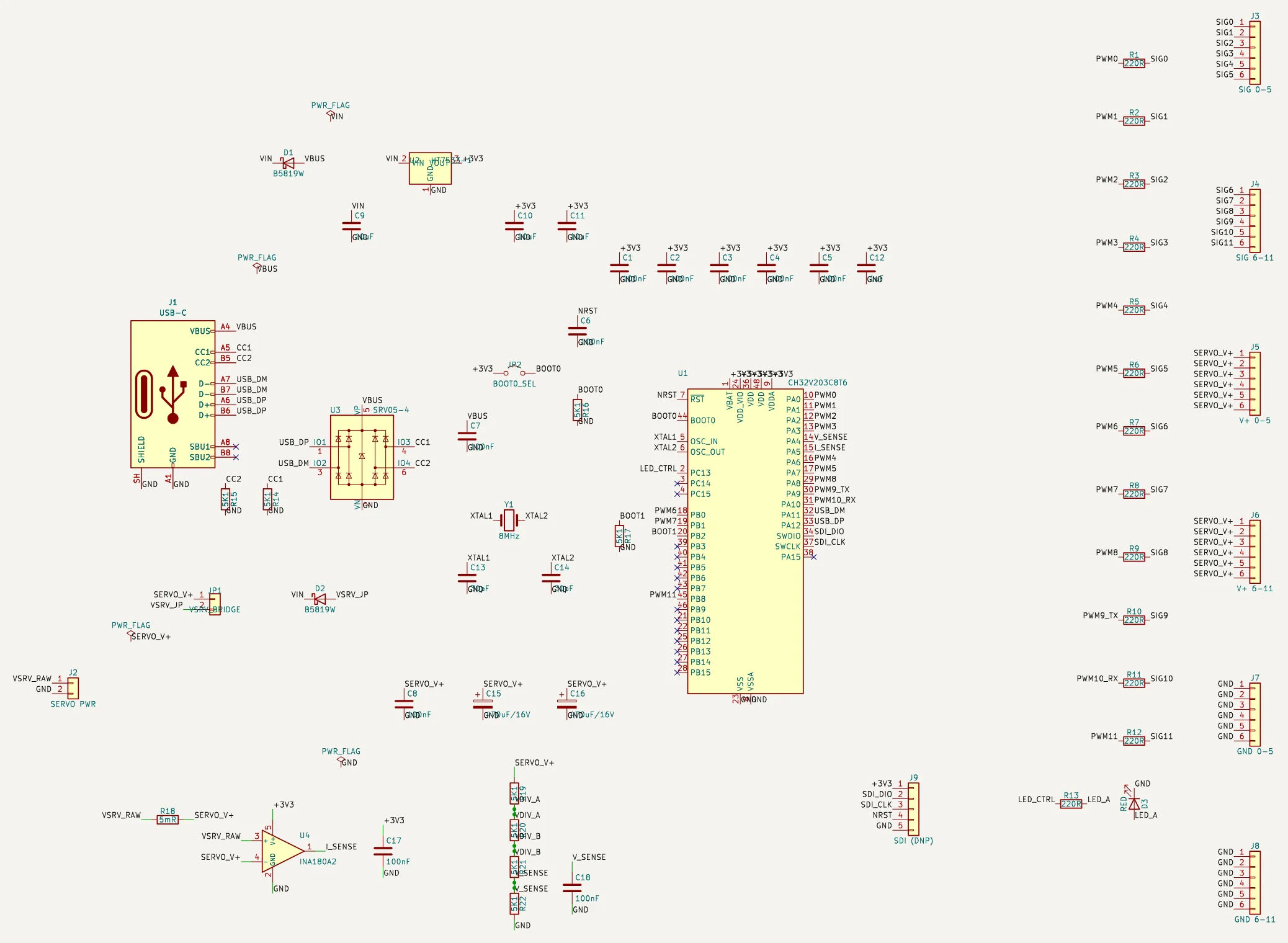
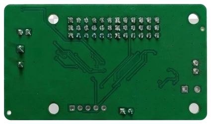
Click to enlarge. Two-layer board, all parts on the top side, designed in KiCad. Schematic, PCB, firmware and tools: GitHub.
Uploading new software
The board has its own USB bootloader, so updates need no programmer and no jumper.
- Normal update – in the GUI open the Firmware tab and press Flash firmware (takes about 3 s). The firmware file comes with the GUI download.
- Blank chip or recovery – fit a jumper on BOOT0_SEL, plug in USB and flash the full image with the WCH ROM bootloader (wchisp). Then remove the jumper and replug.
Servo GUI
One file, no install, for Windows and Linux. Also runs without a board (--mock) for trying things out.
- Channels – switch each channel on, drag its slider; set name, travel limits and speed per channel, or make channels 0–7 analog inputs
- Rail – live current and voltage, 10 s graph with peak hold, overcurrent / undervoltage limits, CSV recording
- Poses & sequence – save positions as named poses, play them back with move and hold times, upload the sequence to run on the board
- Script – editor with syntax check for board scripts, upload, run, autorun at power-up
- Firmware – update the board over USB with one click
- STOP – space bar or Esc switches every servo off
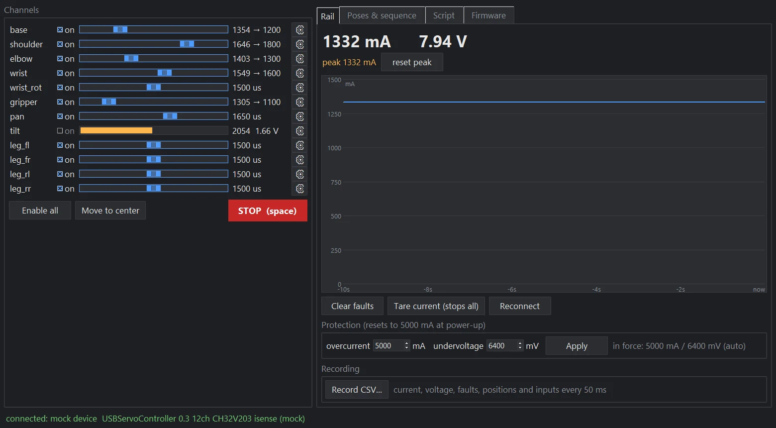
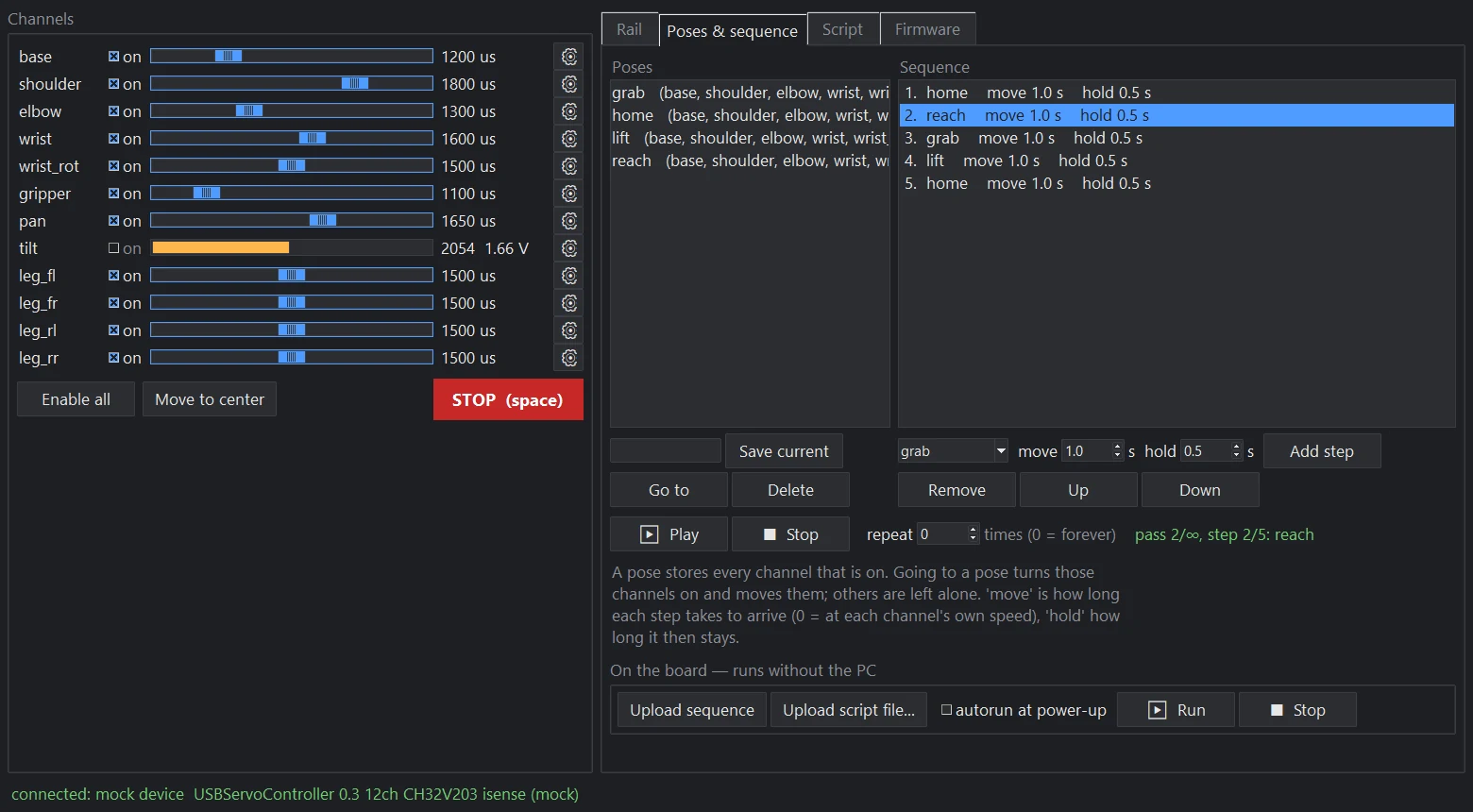
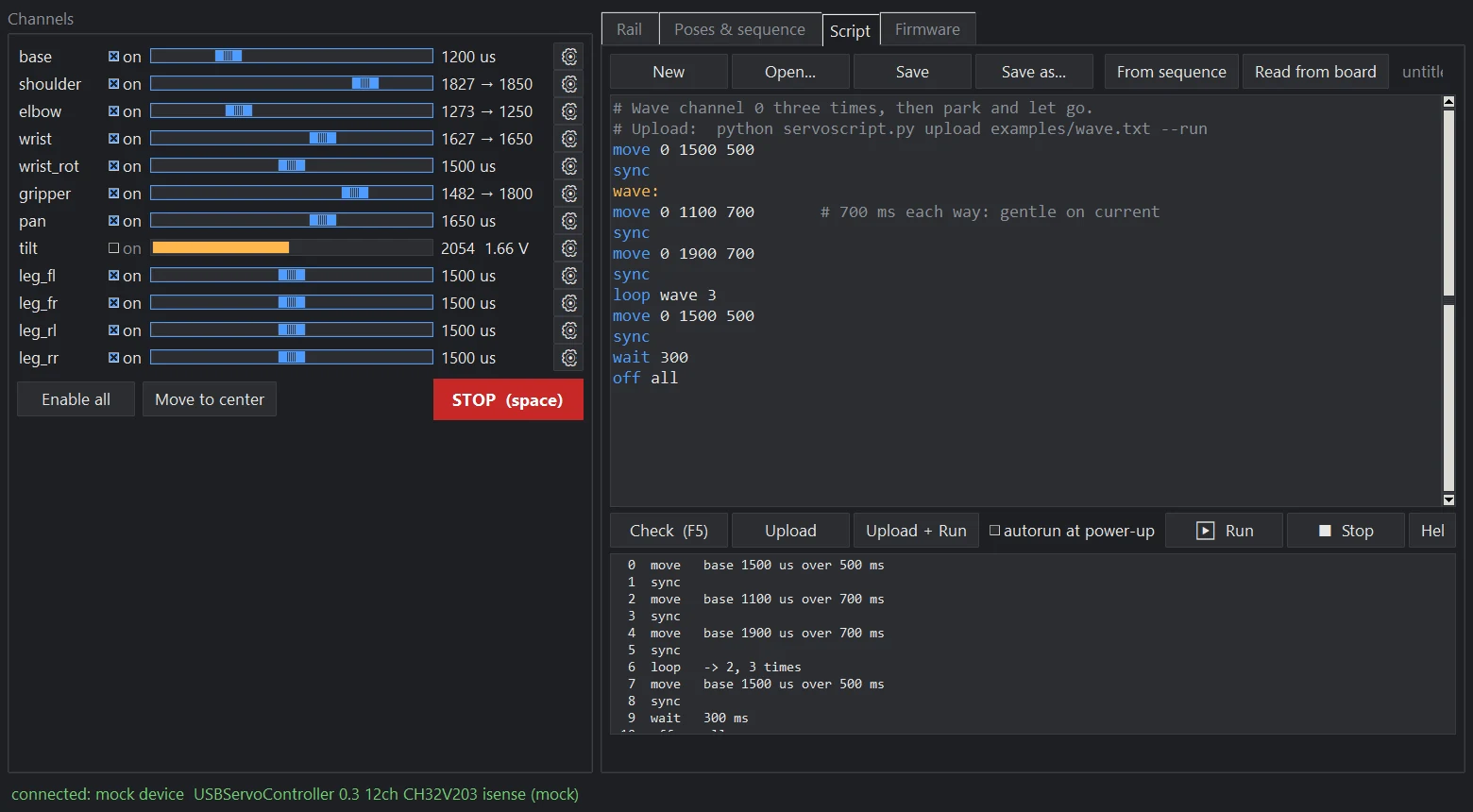
Click a screenshot to enlarge.
Download
Windows (x64)
Linux (x64) – add your user to the dialout group for serial access
Firmware 0.4 – application image, for the GUI's Firmware tab
Firmware 0.4, full image – bootloader + application, for a blank chip or recovery
All releases on GitHub
Other tools
Python library and command-line tool, a script compiler for on-board scripts, and an MCP server that lets an AI agent drive the servos. Any serial terminal works too, e.g. send S 0 1500 to centre channel 0.